


Operating instructions
This type of loom has a high degree of automation. By pressing the start button, a series of operations will be performed automatically, including: slow-moving and pick finding, adjusting the warp tension, etc., and the machine will start immediately after these actions are performed!
A series of slow motions may also be performed after the loom is stopped.
During automatic operation, the warning lights on both sides of the machine beam will flash, for safety reasons, when the warning light is flashing, it is forbidden to touch the machine!
In an emergency, you can press the stop button or the emergency stop button to interrupt all operations.
1 Control Box Button Description
The left side of the control box has a rotary switch, which is the main power switch. There are five buttons on the right side of the box. From left to right, it is the SYNC button, backward button, forward button, emergency button and start button.
1.1 Main Power Switch
Turning this switch clockwise turns the control box's power on and turning the switch counterclockwise turns the power off. After turning off the power, wait at least 25 seconds before turning on the power to the control box to ensure that the system is fully powered down. Otherwise, the system may appear after let-off motor or take-up motor failure alarm or other abnormal state, it is important to pay attention to this point.
1.2 Start Buttons
Green button, when this button is pressed, the button lights up, indicating that the main loop is switched on. When the status window screen is displayed on the system screen, pressing this button will turn on the main loop, the oil pump motor will work and the warning light will blink. After a few seconds, the motor driver board will be fully powered on. When a button requiring machine movement is pressed, Such as starting button, slow or pick finding button, the main motor will start. If the loom no special circumstances, the screen loom state should be "standby."
1.3 Backward and Forward Buttons
Press the backward button, let-off motor will start to loose the warp. When the warp tension is less than the minimum set tension, backward button does not work.
Press the forward button, let-off motor will start to tighten the warp. When the warp tension exceeds the set tension of double, tight button does not work.
1.4 SYNC Buttons
Black button, when the SYNC button, the take-up roller and warp beam will be synchronized forward rotation, the tension remains unchanged
2.2 Loom Button Description
2.2.1 Power Supply Connection for Control Box
After pressing the start button, the loom will automatically execute the preset driving action before driving (see section 3.4.7 for details). At the same time, the four-color signal light will blink rapidly from top to bottom, and then start running.
The car button is invalid on the following occasions:
• When a serious alarm is not released
• Emergency stop button, stop button pressed or main loop not activated
• The current angle is not within the driving range
2.2.2 STOP Buttons
If the button is pressed during weaving, the loom will stop at the preset stopping angle of manual stopping. After the brake loom automatically perform the preset action.
Special Instructions:
If the loom in the parking process, press and hold the stop button for more than 2 seconds, the loom will stop the follow-up action, you need to manually find the weft.
Pressing the stop button while in slow motion will stop immediately.
When finding the pick and the motor shaft is extended, press and hold the stop button. The loom will suspend the pick-finding and pick-finding movement. The screen will prompt "Find weft and hold" and the yellow light flashes. At this moment, pressing any pick-finding and pick-finding button will continue to complete the remaining search pick-finding movement, other buttons do not work.
2.2.3 PFF/PFR Buttons
Press the PFF,PFR button in standby mode, the loom will automatically move slowly to 330 ° or 30 ° to start the positive or negative direction for pick-finding, then the loom moves slowly to the desired pick-finding position (Default 40 °), the yellow signal flashes during this process. Loom to reach the pick-finding position when the action stops, the warning light goes out, you can remove discarded picks. If in the process of pick-finding press the stop button, the loom will suspend the current pick-finding movements. When the PFF and PFR buttons are pressed again, the weaving operation will continue to be interrupted. In the following occasions, PF button is invalid:
• When the current position is not finding for weft (levelling+ 160 ° ~ 270 ° is non-pick-finding)
• Emergency stop button, stop button pressed or main loop not activated
• Loom not synchronized
• There is an alarm that prohibits loom movement
2.2.4 SMF Buttons
Press the button while in standby mode, the loom will move slowly and forward. At this moment, the warning light does not flash, and if you release the button, it will stop. At this point, if the stop button is pressed, the local stop immediately.
The SMF button is invalid on the following occasions:
• Emergency stop button, stop button pressed or main loop not activated
• There is an alarm that prohibits loom movement
2.2.5 SMR Buttons
Press this button in standby mode, the loom will move backwards. As long as it is held down, the loom will retreat all the way to the set resetting angle (eg 320 °). Pressing the stop button during auto reset will terminate the auto reset action.
The reset button is invalid on the following occasions:
• Emergency stop button, stop button pressed or main loop not activated
• The current angle is greater than 200 ° and less than the reset angle
• There is an alarm that prohibits loom movement
2.2.6 Emergency Stop Buttons
Pressing this button at any moment, the loom will stop immediately, all the buttons are locked, but the control box still has electricity. All machine movements are locked until the emergency button is rotated 1/8 turn clockwise to unlock it. Use this button only in the event of an emergency or for safety reasons and must never be used as a stop button.
2.3 Warning light status description
The warning light is a red LED on both ends of the loom beam. When the loom is stopped for some reason after the push button is pressed or the start is stopped, the loom will perform a series of tasks according to a predetermined procedure. At this moment, the red warning The light will flash rapidly to remind the operator. Until the loom stops completely, the warning light will stop blinking, then the operator can proceed to the next step.
Note: It is extremely dangerous to operate the loom during the flashing of the warning light, which may endanger the personal safety!
2.4 Loom button abnormal status prompt
When the system detects that the operation button of the loom has been pressed for a long time, it will display the message that the related button has been pressed on the main screen of the screen, and can judge whether the related button is stuck and can not be reset according to the prompt The situation, to prevent loom unexpected movements.
2.5 Loom signal status description
In order to facilitate the loom factory to check the fault or loom state according to their habits, the display state of four color lamp can be set freely, each lamp respectively have four kinds of state: Off, On, Slow flash, Fast flash. Each state of loom can be independently assigned a state of each color lamp.

The factory configuration is as follows:
|
Loom state |
Four-color lamp state |
|
Warp |
Red light |
|
Warp Fixed |
Slow flashing red light |
|
Weft Stop |
Yellow light |
|
Pick Finding |
Slow flashing yellow light |
|
Hand Stop |
Green light |
|
Full Piece Stop |
Green light |
|
Weaving Stop |
Slow green light |
|
Bobbin Break |
White light and yellow light flash slowly |
|
Continued Fault |
Slow flashing green light |
|
Temporary Fault |
Blinks green for 5 seconds |
|
Warp Detection Closed |
The red light is on |
|
Filling Detection Closed |
Yellow light is always on |
|
Running Ready |
Four lights cycle flashing from top to bottom |
|
Encoder Fault |
Four lights cycle flashing from top to bottom |
|
Power Off Portecting(Need to re-power) |
Four lights cycle flashing from bottom to top |
|
The loom is powered on for the first time after power-off |
Four lights cycle flashing from bottom to top |
|
Call mechanic |
White light |
|
Machine status |
Slow flashing white light |
|
Weaving state |
All off |
When a mechanic input signal is tested, the red light flashes when there is a new input signal.
The status description in the above table only makes sense if the loom is in a specific single state. When two or more weaving machine states occur at the same time, for example, when the stop button is pressed and the weft cutting detection function is turned off, the green light and the yellow light will be on at the same time. For the situation that many of the semaphores are on at the same time, Refer to the relevant information on the screen to determine the cause.
Chapter 3 Operation of Display Terminal
3.1 Introduction of the Display Terminal
3.1.1 About the Touch Screen HMI
Various parameters of loom settings, production data, organization of the preparation process, as well as loom fault alarm are displayed through the user interface. The system uses 10.1-inch color LCD touch screen, elegant appearance, delicate screen, stable and reliable performance.
The LCD screen will turn on the backlight during normal operation. After a few minutes of operation, the backlight will automatically turn off and enter the power saving mode. Backlight lit time and whether to turn on beeper operation beeps can be set in the menu.

Touch Screen HMI
3.1.2 Digit and Character Input
If you want to input a number or a character in the input box, just press the corresponding input box and a keypad will appear. Input the content you want and press the key "ENTER" to confirm. The key "<-" is a backspace key and the key "CLR" is used to used to clear the input. The top of the keypad is an area that displays the input range of the input box and you can not input a value beyond the limit.

Number and Character Keypad
3.1.3 User Authorization Setting
This control system has multi-level authorization management function, modifications for different data need different operation authorizations.
1) The division of operating authority
Operators: This is the default permissions after system startup, without logging in. Under this authority, the user can view various parameter settings and statistical records of looms and other data, and can perform shift operations.
Mechanic: This permission needs to be logged in. Under this authority, the user can modify various parameter settings of the loom, adjust the loom status, edit the flower-shaped file, but can not modify certain key parameter settings.
Weaving Mill: This permission needs to be logged in. Under this authority the user has all the rights of the mechanic and can adjust some of the loom settings.
Manufacturer: This permission requires login. Under this authority, the user can modify any parameter setting of the loom and carry out any operation.
2) User Login
If the user wants to have the rights of other drivers need to login. Click the key icon at the top of the "Status Window" screen to enter the "User Management" screen, as shown below:

User Management

Logon
In this screen, there are three options: user login, logout and password change. The user name of the currently logged in user is displayed below the screen. Click the [User Login] button. In the dialog box that is displayed, select the user name you want to log in to and enter the correct password. After the login is successful, the user name is displayed at the bottom of the current screen, and the user can perform related operations. When the login time expires, it will automatically log out.
The user can also choose to log in directly when they need to do the operation. At this time, the related operation can be performed according to the prompts on the screen.
3) Logout
When the operation of high-level permissions is completed, please promptly
withdraw from the current permissions to ensure that the data security changes. Click the [Logout] button in the "User Management" screen to log off the current authority.
4) Change Password
In the case of a user login, the login user can modify his own password. The specific method is to click the [Password Change] button on the "User Management" screen, enter the old password, new password and new password in the pop-up "Change User Password" dialog box. If there is no error message, the password is changed successfully.

Change Password
5) Retrieve Password
If you forget your password, you can retrieve the password of the corresponding user level. The specific method is to click the [Recover Password] button on the "User Management" screen, enter the authority password in the pop-up "Password Input" dialog box, enter the password retrieval interface, select the corresponding user and click View to view the password.

Password Retrieve
3.2 Start-up of the Control System
When the control box is powered on, the system will enter the startup state. The touch screen will display the startup screen and display the company logo, now the control system is in the self-test state. After more than ten seconds, if the system startup is normal, the screen will display the main screen, the status window, otherwise it will prompt error information.

Start-up screen
3.3 Status Window
After normal startup, the HMI will display the main screen, the status window. The entire screen is divided into six regions, time and language display area, the system status area, the production data display area, the fault display area, function select area, and more information display area. Detailed below.

3.3.1 Time and Language Display Area
The area is located on the top right of the status window, displays the current system time and language, including the year, month, day, hour, minute, second and week. Since the control system use the time as a reference, please calibrate the system clock after first time power-up. Click the flag icon  to switch the language.
3.3.2 Status Icons
This area is located on the top right of the status window, including the following three parts (left to right):
1) User Login: When you need to call a mechanic, you can click on the wrench icon  on the screen, the wrench icon will flash and the yellow signal lamp will light up. When you click on the icon again, the icon will stop flashing and the yellow signal lamp will go off.
2) Calling mechanic: When you need to call the mechanic, you can click the wrench icon on the screen. At this time, the wrench icon  will flash and the white signal will light up. When the icon is clicked again, the icon stops flashing and the white signal light goes out.
3) U disk status indication: U disk icon  will be displayed in the status icon area when the system detects that a U disk is inserting in USB socket on the control box side, and vice versa.
3.3.3 Production Data Display Area
This area shows the production data and the current status of the loom.
Speed: Shows the current speed of the loom.
Pick Density: Shows the current pick density and density number. The density number will be always 0 when the multiple pick density function is turned off.
Target Tension: Shows the target tension of the warp yarns.
Warp Tension: Shows the current tension of the warp yarns.
Shift: Shows the current shift. Click the shift area on the screen to set current shift.
Shift Output: Shows the production of current shift.
Preset Length: Show the cloth length to be woven for full piece stop.
Piece Length: Show the length of woven cloth.
Position: Shows the machine angle position.
Loom State: Shows current state of the loom. See section 3.3.6.
Stop Reason: Shows the last stop reason of the loom. See section 3.3.7.
Dobby Pattern: Shows the name of current using dobby pattern.
3.3.4 Fault Display Area
The area is located at the bottom left of the screen and six faults can be displayed simultaneously. When the faults are more than six, you can view them through the log.See section "4.1 Alarm Message" for the specific content.
Note: 1) The slow motion and pick finding action will be prohibited when there are alarms about ELO-ETU, drive board and jacquard.
2) When loom synchronous failure alarm occurs, the loom will not be allowed to find the weft.

Alarm prompt
3.3.5 Function Select Area
This area is located at the bottom of the screen, including the following eight function menu:
1) Pattern: Dobby and Color pattern programming.
2) Param: Set the technological parameters of the loom.
3) ELO-ETU: Set the ELO-ETU parameters.
4) Stat: View or clear the statistics data.
5) Test: This operation should be done after the main motor is closed. This function includes input signal monitoring, output signal test, ELO-ETU signal monitoring, dobby test, loom synchronization, crossing position setting, test SR motor.
6) Aux: The auxiliary function includes pattern adjustment, time setting, view system information, output signal monitoring, backlight and beeper setting, Cam levelling, drive board status monitoring.
7)Log: To view the recent fault and operation records of the loom.
8) Piece: This menu includes nine items, preset length, piece length unit, use external end signal, full piece stop, length unit, cloth length factor, full beam length setting, reset piece length and beam length.
3.3.6 Loom State
Loom state displays in the production data area, indicating the action or state of the loom.
1) Slow Motion: The loom is moving forward at very low speed.
2) PF Forward: Pick-finding forward now.
3) PF Reverse: Pick-finding reverse now.
4) PF Not Finish:If last pick finding didn't finish, this message will display on the screen before running. One time complete pick finding must be done before running to ensure that the pick finding mechanism is well.
5) Prewinder Alarm: One of the prewinders lacks pick yarn. Can't start the loom at this time.
6) EMER Button: The emergency button is pressed now and the main loop is cut off.
7) Full Piece: The preset length is reached. Must clear the piece length in the "Piece Setting" window before running.
8) Power Lost: Power lost during fast running. It's better to adjust pattern. When the loom powers on again, the signal lamps will flash from bottom to top repeatedly. At this time, perform slow motion to make the grippers be at both ends and perform PFF once, now the signal lamps will not flash. Then perform PFR several times until the pattern is correct.
9) PF Pause: Pick finding pauses as the stop button is pressed. You need to press the PFF or PFR button again to finish the pick finding, otherwise the loom will not response to other actions.
10) Loom is Out of Sync: Loom and rotary encoder and the opening mechanism has not been synchronized, this time the loom can not perform any action, the need to perform loom synchronization.
11) Power Lost-PFR: That a loom on the last power outage occurred in the anti-Wei, then need to re-proofing pattern. When the loom is switched on again, the loom lights flash in sequence from bottom to top, indicating that a power outage occurred in the opposite direction. At this time should be slow to make the sword head at both ends of the loom, and then is looking for a weft operation, this time the signal is no longer flashing. Then find the pattern several times until the pattern is correct.
12) SM Reverse: Reverse slow motion in the loom.
13) ELO-ETU Not Ready: The ELO-ETU system is not ready for startup within the specified time.
14) Warp Broken: The system detects broken warp signal as warp detection function is on.
15) Warp Broken 2: The system detects broken warp signal 2 as warp detection function is on.
16) Not at Start Area: The loom position is larger than 120° and less than 270° when the start button is pressed.
17) Running: The loom is running.
18) Main Motor Off: The main motor is off.
19) Ready: The main loop is working and the loom is ready for start.
20) Take-up Forward: Manually carry out tight operation.
21) Take-up Backward: Manual sliver operation.
22) Let-off Forward: Manually perform the warp beam relaxation operation.
23) Let-off Backward: Manually perform the warp tightening operation.
24) Let-off Forward 2: Manually perform the second warp beam relaxation operation.
25) Let-off Backward 2: Manually perform the second warp tightening operation.
26) Cloth Forward: Manual cloth forward operation.
27) Cloth Backward: Manually move the cloth back.
28) Safe Protection: Indicates that there is no safety protection in the event of a failure of the loom.
29) Reset Not Finish: The loom has not finished resetting.
3.3.7 Loom Stop Reason
Stop reason is displayed in the production data display area indicating the last stop reason.
1) Warp Stop: Stop due to warp breakage.
2) Weft Stop: Stop due to weft breakage.
3) Double Weft: Stop due to double weft.
4) Hand Stop: Stop by pressing stop button.
5) Full Piece: Stop when the preset length is reached if the "Full Piece Stop" function is opened.
6) Emergency Stop: Stop by pressing emergency button.
7) Bobbin Break: Stop due to one of the prewinders lacks pick yarn.
8) Loom Fault: Stop due to loom error, e.g. low oil pressure, main motor overload and so on.
9) ELO-ETU Fault: Stop due to ELO-ETU fault.
10) Drive Board Fault: Stop due to drive board fault.
11) Power Lost: Power lost during fast running. Adjusting pattern should be done after power on.
12) Unwanted Weft: There is a weft yarn woven into the fell in the empty weft cycle.
13) No Double Weft: Weft breakage happens during double weft cycle.
14) MCB Instruction Err: Stopping due to MCB hardware failure.
15) Safe Curtain: Stop due to the protection signal of safe curtain.
16) Jacquard quantitative parking: The machine stops when the jacquard weaving task is completed.
3.3.8 More Information Window
Click on the text ">>More" on the bottom right of the status window, the "More Information" window will appear. This screen displays the following contents:
Dobby Line: Dobby line number and dobby data
Color Line: Color line number and color data
Total Picks: Total picks woven since the loom leaves the factory
Last Weft Stop Angle: The angle where the system detects weft breakage during the last weft stop
Brake Start Angle: Shows the angle where the loom begins to brake during last stop
Brake End Angle: Shows the angle where the loom speed becomes to zero during last stop
Brake Distance: Shows the braking distance of last stop

More Information Window
3.3.9 Change Shift
If the shift change mode is manual, click on the letter "A" or "B" or "C" or "D" on the right side of the text "Shift:" in the status window, and select the shift you want on the pop-up window, then press [OK] to change shift. All the statistics data of the new shift will be cleared right after shift change.
If the shift change mode is automatic, the above operation is invalid, the system will change shift automatically according to the setting of the shift time.
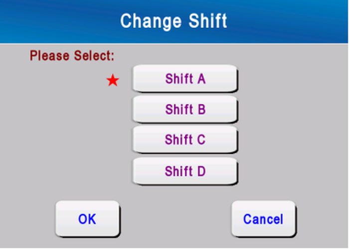
Change Shift
3.4 Parameters Setting
Press [Param] in the status window to go to the "Parameter" screen. There are twelve items in this screen and press the corresponding item to enter the window for each function.

3.4.1 Prewinder Setting
Click item 1  on the main screen of parameter setting to enter the parameter setting screen of weft feeder

Prewinder Setting
|
No. |
Parameter |
Description |
Default |
Range |
|
1 |
Prewinder OK Level |
Set the ready signal of the weft feeder to be high or low. |
Low Level |
Low/High Level |
|
2 |
Prewinder Switch-Off |
Set whether to use the automatic weft supplement function. |
OFF |
OFF/ON |
|
3 |
Color Output Replace |
Set the color selection replacement function |
OFF |
OFF/ON |
|
4 |
Manual Switch Channel |
When the weft feeder has no weft and the weft selection needle has been switched to the equivalent weft selection needle, if the manual switching weft compensation function is turned on, when the weft feeder is connected and ready, the weft selection needle will not automatically switch back to the pattern The weft selection needle of the type setting will not be switched until the button on the bottom right of the screen is pressed in the status window screen during driving or standby. Conversely, when the manual switch weft compensation function is turned off, when the weft feeder is ready, it will immediately switch back to the weft selection finger of the pattern setting. |
OFF |
OFF/ON |
|
5 |
Auto Channel Mixing |
When this function is turned on, the weft selection needles that do not lack yarn in the same equivalent weft selection group will work in turn to achieve the effect of mixed weft; |
OFF |
OFF/ON |
|
6 |
Replace Color |
Set the number of the color selection pins corresponding to the replacement of the color selection finger. For example, C1-C2 means replacing C1 with the C2 color selection pins. |
Same as self number |
C1 – C12 |
|
7 |
Group Number |
Set the equivalent weft selection group for automatic weft supplementation. If it is set to "*", it will not participate in the grouping. |
* |
A - F |
|
8 |
Prewinder No |
When setting the weft feeder associated with a certain weft selection needle to have no weft yarn, it replaces the equivalent feeder number that completes the color selection function. |
Same as self number |
1 - 8 |
Automatic Prewinder: It means that when a prewinder associated with an optional prewinder has no weft, the selected equivalent weft needle is replaced to complete the color selection function.
At this point loom lights will continue to flash to indicate this happens. If the
missing prewinder state returns to normal, the corresponding prewinders will return to normal weaving.
Tip 1: Automatic weft insertion is only possible if the prewinder is equipped with a weft thread sensor. In order to make the automatic filling work properly, the weft feeder must be correctly connected to the corresponding weft selecting needle, that is, the prewinder number must match with the weft picking weft number one by one.
Tip 2: When auto-fill setting, if you want to do only partial fill-in operation, then the reserve number of the weft feeder that does not need to do fill-in operation can be set as its own number.
Tip 3: When the automatic fill-in function is enabled, you should pay attention to check the settings of the automatic fill-in parameters after modifying the color-selecting pattern to ensure the automatic fill-in function is normal.
3.4.2 Filling Detection
Click on item 2 in the parameter setting screen to enter the filling detection setting screen.
Friction between the yarn and the weir piezoceramic hole produces an electrical signal that is sent to the processor and amplified, and the sensitivity of the signal is adjusted on the display.

Press [Save] button to save the parameters and press [Back] button to return to the "Parameter" screen. If you return directly from this screen without saving the parameters, then the changes are invalid. The settings of other parameters are the same.
|
No. |
Parameter |
Description |
Default |
Range |
|
1 |
Filling Detection |
Weft detection function switch. |
ON |
OFF/ON |
|
2 |
Double Filling Detection Filter |
|
4 |
1 - 30 |
|
3 |
Double filling detection swith |
|
ON |
OFF/ON |
|
4 |
Filling Detection Filter |
Set filling filtering time, the greater the value the lower the sensitivity, the less likely to detect filling. |
4 |
1 - 30 |
|
5 |
Filling Detection Zone1 |
The first pick finding of the starting point of the end of the angle. |
110/160 |
100 - 160 |
|
6 |
Filling Detection Zone2 |
Second weft zone start angle and end angle. |
240/290 |
230 - 310 |
|
7 |
Filling Detector Gain |
To set the amplification degree of the output signal of the weft yarn detector, it can be set separately for each color channel. |
8 |
0 - 15 |
|
8 |
FD End Angle |
The end angle of weft detection corresponding to each color selection |
290 |
240-320 |
The system supports weft detector with anti-double weft function. When more than one weft arrives at the cloth fell, the weaving machine will stop immediately. 
detection parameters adjustment:
1) End of the weft angle adjustment
Turn the weaving machine until the right sword head yarn, check the loom angle at this time, for example, 300 °, subtract 10 ° from the angle, the value is the end of the weft angle. In this example, this value is 290 °. The end of the probe should be set as late as possible so that the probing time is as long as possible. However, the weft may be released at different times as the head of the sword vibrates as it enters the guide, so the detection must be completed earlier.
2) Filling detector gain adjustment
Before normal use of the weft detector, check whether the voltage value of the
gain control signal of the weft detector (voltage between pins 4 and 4 of the four-core connector J3 on the main control board) is between 1 and 5 volts, This value can be adjusted by the weft detector gain parameter. The larger the value, the larger the voltage value of the gain control signal, and the greater the output signal strength of the weft detector, the easier it is to detect the weft. The different weft detectors correspond to different values of this parameter, generally in the range of 3 - 12, with a default value of 8.
Into the machine test input signal monitoring screen, quickly pull a weft to observe whether the system detects the weft signal, if there is no weft signal, you should gradually adjust the parameters until the weft signal is detected.
If we need to change the sensitivity of weft varieties, the recommended adjustment is to set the weft pick-up gain to a higher value (for example, 10) in order to drive, and then gradually reduce the gain until the weft looper stops And stop, and then increase the value of 2 to 3 units.
3) Filling filter value adjustment
The filling detection includes filling detection and double filling detection. The filling detection time can be set independently for each filling picking channel. The filling and double filling filter values are adjusted by 0.5 ms. If there is filling stop and actually not weft, filling detection is too sensitive, then we can adjust the value of "weft and weft filter" of the signal of the road and vice versa; if there is double filling stop, Double filling detection is too sensitive, then the "double filling filter" value adjusted up, otherwise small; if this adjustment is still not satisfactory, you can properly adjust the "weft detector gain" The value of the smaller the value tends to be reported off filling stop, the greater the more tend to double filling stop.
Weft insertion filter values must be set as low as possible, but depend on the weft's roughness. For smooth weft yarns, this value is 1 to 4; for rough weft yarns, such as slub yarns, this value must be increased (eg 8 to 10) because this weft yarn can not always be in contact with the porcelain holes.
Note: In order to ensure the normal operation of the weft feeler, the guide rod in front of the feeler must be adjusted so that the weft always remains in contact with the porcelain eye of the weft feeder.
3.4.3 Warp Detection
Click on item 6 in the parameter setting screen to enter the warp detection setting screen.

|
No. |
Parameter |
Description |
Default |
Range |
|
1 |
Warp Detection |
Warp detection switch. |
ON |
OFF/ON |
|
2 |
Warp Detection Filter |
Set the value of warp detection filter, the greater the value is not easy to detect menstruation. The unit is millisecond. |
10 |
1-40 |
|
3 |
Warp Detection Delay |
Set after driving a few picks does not detect menstruation. |
0 |
0-30 |
Description:
"Warp detection filter" refers to the control system to warp yarn input electrical signal control reaction. The filter value can be adjusted to ensure that the weaving machine can stop at any breakage. Filtration value of a total of 40 settings, the greater the setting value the lower the sensitivity, that is, the intensity of the electrical signal control system usually ignore, that is less prone to error stop phenomenon, but the setting value is too large may produce after menstruation Prolonged non-stop phenomenon; the other hand, the smaller the setting value, the higher the sensitivity is, the less likely to cause the phenomenon of non-stop menstruation, but the setting value is too small may cause a wrong stop phenomenon. Medium sensitivity for most fabrics, with a default of 10.
3.4.4 Filling Presenter
Click on item3 in the parameter setting screen to enter the weft detection setting screen.

|
No. |
Parameter |
Description |
Default |
Range |
|
1 |
Max Filling Needle Num |
Set the maximum number of weft need to control. |
[8] |
[8]/[12] |
|
2 |
Filling Needle Down |
Select weft start drop angle. Setting this value too high may result in the pick-warp falling too late to allow the pick-weft sword to weave in the filling |
300 |
220-340 |
|
3 |
Filling Needle Up |
Picked weft began to raise the angle. |
100 |
60-170 |
|
4 |
Empty/Double Filling |
Set whether to allow double filling and empty weaving. Double filling and pick finding in the pattern editor programming settings |
OFF |
OFF/ON |
|
5 |
Filling Presenter Up Mode |
Choose whether the needle is lifted up or lifted halfway up. If you select half lift, then when the half-lift the color-selecting needle is selected again, it will fall directly from the half-lift position. If the half-lift color-selecting needle is not selected, Lift, the color selection needle in the lift without lifting the state directly lift the top. |
Complete |
Complete/Half |
|
6 |
Filling Presenter Always ON |
Set whether the stepping color selection motor remains on after it is lifted. |
OFF |
OFF/ON |
Color Drive Par:Click to enter the color selector drive parameter interface, set the running current, standby current, and travel parameters
3.4.5 Shed Movment
Click on item7 in the parameter setting screen to enter the weft detection setting screen.

|
No. |
Parameter |
Description |
Default |
Range |
|
1 |
Harness Frame Number | To set the harness frame number to control. |
16 |
1 - 20 |
|
2 |
Crossing Position | To set the angle of crossing position. |
315 |
290 - 345 |
|
3 |
Number of Using Lenos |
Set the number of Leno to be used |
2 |
2 - 5 |
|
4 |
Leno Startup Correction 1 |
Set the modification coefficient of the first weft skein after starting up |
80 |
75 - 100 |
|
5 |
Leno Startup Correction 2 |
Set the correction coefficient of the second weft skein after starting up |
95 |
75 - 100 |
|
6 |
Leno Disabled For SM |
Set up the slow motion prohibition function of the Leno |
Off |
OFF/ON |
|
7 |
Left Leno Crossing Angle |
Set the angle at which the opening of the Left Leno is closed. |
290 |
250 - 350 |
|
8 |
Right Leno Crossing Angle |
Set the angle at which the opening of the right Leno is closed. |
290 |
250 - 350 |
|
9 |
MID-1 Leno Crossing Angle |
Set the angle at which the opening of the MID-2 Leno is closed. |
290 |
250 - 350 |
|
10 |
MID-2 Leno Crossing Angle |
Set the angle at which the opening of the MID-2 Leno is closed. |
290 |
250 - 350 |
|
11 |
MID-3 Leno Crossing Angle |
Set the angle at which the opening of the MID-3 Leno is closed. |
290 |
250 - 350 |
Leno pattern settings:
The control system supports single-sided stroke pattern programming, the maximum number of lines of 30 lines. Press [L-Leno] or [R-Leno] button to enter the pattern programming window of the selected edge on the opening movement screen. Edging pattern input and editing and multi-arm pattern, the specific reference "pattern programming" chapter.
Leno pattern programming:
Each row next to the pattern line number in the hemming programming screen corresponds to an action of the hemming device. The "1" column indicates the up-and-down position where the front of the hemming edge is located, and the "2" The back of the heddle where the upper and lower position. Clicking on a small square in the Edges Editing area sets the mark (white) or unmark (gray) at the corresponding position, "white" indicates the heddle bar is up and "gray" indicates the heddle bar. The two levers must be moved in the opposite direction.
Winding pattern maximum number of lines can be set to 30 lines.

Operation:
Leno device weaving pattern must be synchronized with the ground organization. This is important for the quality of the edge as well as the first and last warp tension. Each leno pattern can be moved forward or backward by one or more steps by pressing the [UP] or [Down] button to synchronize with the ground organization. Press the [Origin] key to return the leno number to 1.
Current Number:
Current leno of the pattern performed by the serial number.
3.4.6 Slow Motion and Main Motor Setting
Click on item10 in the parameter setting screen to enter the weft detection setting screen.

|
No. |
Parameter |
Description |
Default |
Range |
|
1 |
Remove Filling Angle |
When the weft is found manually, the weaving machine automatically moves to this angle at the end of the filling picking to facilitate the removal of the filling |
40 |
20~50 |
|
2 |
SM Reverse Mode |
Set the mode of movement of the loom when the reverse local button is pressed. Automatic: loom back to the set automatically reset to the reset angle. Manual: Hold down the reverse local button, the loom moves backwards slowly until the button is released or the reset angle is reached. Manual: Hold down the reverse local button, the loom moves backwards slowly until the button is released or the reset angle is reached. |
Auto |
Auto/Manual |
|
3 |
Reset Angle |
Set loom reverse slowest stop angle or loom start angle. |
325 |
290-340 |
|
4 |
Brake Angle Warning Upperlimit |
From the beginning of the brake to loom stop completely loom total angle exceeds this value will alarm. |
350 |
60-720 |
|
5 |
Start Button Mode |
Start Button Mode Press Once] : click it once [Press 2 Seconds]: Press for two seconds |
Press Once |
[Press Once] /[Press 2 Seconds] |
|
6 |
Run Speed Up Mode |
Set fast speed acceleration mode |
[Normal] |
[Normal]/ [ Fast ] |
|
7 |
LV-Brake Advance Release Time |
Set the amount of time that the auxiliary brake releases early when the loom begins to move to ensure that the auxiliary brake is fully released. |
150 |
50-999ms |
|
8 |
LV-Brake Release Time |
Set the time for the brake to be delayed after the manual idle operation. |
2500 |
500-5000ms |
|
9 |
Pick Finding Speed |
Set loom speed during pick finding |
30 |
5-60 |
|
10 |
Manual Slow Motion Speed |
Set the speed of the loom in manual slow motion.. |
10 |
5-20 |
|
11 |
Auto Slow Motion Speed |
Set the speed of the loom when it is automatically slowed. |
30 |
5-25 |
|
12 |
Weaving Speed |
Set the speed of the loom in running |
300 |
150-550 |
|
13 |
Oil Temperature Upperlimit |
When the loom oil temperature exceeds this value, the system will stop alarming. |
70 |
30-100 |
|
14 |
PX-PFP Detection Delay |
Delayed monitoring time of weft finding close state after weft finding is finished |
5 |
5-10s |
Set the variable speed weaving function when setting the variable speed weaving function. After the variable speed weaving function is turned on, the weaving machine will change the speed according to different speed signals, and the speed serial number corresponds to the following speed one by one.
Variable Speed Weave: closed by default

3.4.7 Auto Movement
Automatic movement, here refers to the perspective of loom stopping, stopping and the next pre-drive action, in order to adapt to different fabrics. The stop mode determines the stop mode of non-pick stop and the stop mode of pick determines the stop mode of pick-finding stop. In the parameter setting screen, click the "auto movement" button at the bottom of the screen to enter the auto motion setting screen. Click [Help] to view warp stop/filling stop mode.

Screen display Item Description:
Position: Displays the current machine angle position.
PF position: Displays the set draw weft angle.
Crossing pos: shows the current level position.
Last Braking Distance: Shows the last weft stop or the distance that the loom stops when braking.
The meaning of the parameters on this screen is shown in the table below.
|
No. |
Parameter |
Description |
Default | Range |
|
1 |
STOP |
Loom braking speed of zero moment when the angle position. |
200 |
20 - 350 |
|
2 |
MODE |
Loom after stopping the implementation of automatic movement. loom to the shortest route to automatic machine position, this time to find the combination of slow motion and latitude. Loom to beat the way not to beat the automatic machine position. The loom moves to the automatic machine position with the shortest path, all heddles are flattened. >-PF-<: Loom to beat the way not to beat the automatic machine position, all heddles flat. |
Falling Stop: >-PF-< Warp Stop: |
SM PF >-SM-< |
|
3 |
AMP |
Loom stopping angle after the implementation of automatic movement to reach the position. For weft stops the position is generally near the weft insertion angle in order to remove the weft thread; for the stop position, it is generally near the level of the shed formed by the last weft insertion. |
Falling Stop:320 Warp Stop:320 |
10-50 300-350 |
|
4 |
MODE |
driving the implementation of automatic movement way. loom to the shortest route to automatic driving position, this time to find the combination of slow motion and latitude. PF: weaving loom to beat the way through the automatic movement to the car position.To set the second pick speed after start. |
Falling Stop:SM Warp Stop:SM |
SM PF |
|
5 |
ASP |
Loom can drive angle position. Loom driving automatic movement to this angle start. |
Falling Stop:40 Warp Stop:320 |
1– 50 |
|
6 |
ASO |
Set the number of times to stop before the reed passes before the loom is introduced into the first weft. The positive and negative looms according to the set value will automatically execute forward or reverse rotation. |
Falling Stop:0 Warp Stop:-1 |
-5- 5 |
|
7 |
HalfPicking Enable |
If this option is enabled, when the position of the automatic machine when parking is set at around 30 degrees and the heald frame is required to be all horizontal, the weaving machine will make the heald frame reach the heald at the position of the automatic machine through the wrong tooth, and the motor shaft is kept at the weaving Machine outside, until you press the loom operation button to return to normal weaving. |
OFF |
OFF/ON |
|
8 |
Disable ASP |
If this option is on, the loom will not automatically move the specified drive position while driving, but will drive directly at the current angle. |
OFF |
OFF/ON |
|
9 |
Spec SMR Action |
When this option is enabled, when the loom stop position is less than 250 degrees, the weaving machine will reverse the local car to the automatic machine position without direct forward movement to the automatic machine position. This operation can reduce the number of reverse weft pick-up or loom passing Give up before the number of times. |
OFF |
OFF/ON |
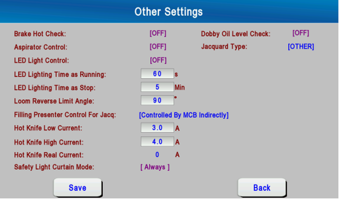
3.4.8 Other Setting
In the parameter setting screen, click the "other settings" button at the bottom of the screen to enter the auto motion setting screen.
|
No. |
Parameter |
Description |
Default |
Range |
|
1 |
Break Hot Check |
Brake temperature detection switch; ON: when the brake is overheated, it will alarm |
OFF |
ON/OFF |
|
2 |
Aspirator Control |
Set whether to control aspirator running in loom stop after stopping. |
ON |
OFF/ON |
|
3 |
LED Light Control |
Set whether to control LED lighting. If you select [ON] in this way, the LED lighting will be powered on during the stop, and the lighting will turn off automatically after a specified time while driving. If you select [ON], the LED lighting is always on. |
OFF |
OFF/ON/CONSTANT |
|
4 |
LED Light Time as Running |
Set how long the LED light will turn off after driving. |
60s |
10-300s |
|
5 |
LED Light Time as Stop |
Set how long to turn off the LED lighting after parking. |
3 |
0-240Min |
|
6 |
Loom Reverse Limit Angle |
Set more than the number of points to prohibit jacquard reverse slow motion. If this parameter is set incorrectly, wrong jacquard may occur in the jacquard machine. |
90 |
40-170 |
|
7 |
Filling Presenter Control For Jacq |
Set the color picker selection control signal. Controlled by jacquard only: color control signal directly provided by the jacquard faucet, and electronic control box MCB has nothing to do. Controlled by MCB Indirectly: the color control signal of the jacquard tap is connected to the electric control board, which controls the operation of the color picker. This way you can flexibly set the motion angle of the color picker to reduce possible mechanical wear. Controlled by MCB Pattern: color control signal provided directly from the MCB, and jacquard faucet has nothing to do. The action of the color picker is programmed through the color selection pattern inside the MCB. |
Controlled By Jacquard Only |
Controlled By Jacquard Only/ Controlled By MCB Indirectly/ Controlled By MCB Pattern |
| 8 |
Hot Knife Low Current |
When selecting the hot knife controller with communication interface, you can set the current that the hot knife passes when the loom moves slowly. |
3.0A |
0.5-15.0A |
| 9 |
Hot Knife High Current |
When selecting a hot knife controller equipped with a communication interface, you can set the current through which the hot knife passes when the loom moves quickly. |
4.0A |
0.5-15.0A |
|
10 |
Hot Knife Real Current |
When selecting a hot knife controller equipped with a communication interface, the current actually passed by the hot knife is displayed. |
-- |
-- |
|
11 |
Safety Light Curtain Mode |
Set the working mode of the safety light grid |
[Always] |
[Always]/[5 Minutes]/ [3 Minutes]/ [2 Minutes]/[ Only Startup] |
|
2 |
Dobby Oil Level Check |
Dobby oil level detection switch |
OFF |
ON/OFF |
|
3 |
Jacquard Type |
Jacquard model selection |
OTHER |
OTHER/STAUBI/BONAS/GROSSE |
3.4.9 Pick Density and Warp Tension
Click on item 4  in the parameter setting screen to enter the pick density and warp tension parameter setting screen. This screen can set up 8 kinds of density and tension, and can set pick density unit.

The pick density signals from jacquard are used to select the one of the eight pick densities and they are usually used on jacquard machines. The ELO-ETU system is controlled by the pick density signals to change current pick density to match the special requirement of the fabric. The pick density signals use 3-bit binary code. When the multiple density function is used on dobby machine, you can program the pick density in pattern editor.
|
No. |
Parameter |
Description |
Default |
Range[Unit] |
|
1 |
Density |
Set the pick density from No.0 to No.7, using for multiple density weaving. f the multiple density function is not used, the No.0 pick density is the executing density. |
300 |
[picks/10cm] 2.0-800[picks/inch] |
|
2 |
Tension |
Set the tension from No.0 to No.7, using for multiple density weaving. the multiple density function is not used, the No.0 tension is the executing tension. The tension 2 is used for the double warp beam loom. |
500 |
picks/10cm or picks/Inch |
|
3 |
Density Unit |
The measurement unit of the pick density. |
picks/10cm |
or picks/Inch |
|
4 |
Multiple Pick Density |
Pick density weaving switch. Programming of latitude and longitude transforms can be set in the pattern editor. |
OFF |
OFF/ON |
|
5 |
Carmming Enable |
Cramming switch. The pry function programming can be set in the pattern editor. |
OFF |
OFF/ON |
|
6 |
Pick Density Factor |
When the actual pick density loom and the theoretical pick density deviation, you can fine-tune this parameter to ensure that the loom pick density in line with the set value. A value of less than 100 will make the actual weft density smaller. |
100 |
85-115% |
3.4.10 Other Setting
Click on item 5  in the parameter setting screen to enter the ELO Setting parameter setting screen.

| No. | Parameter | Description | Default | Range[Unit] |
| 1 | Max Tension | To set the upper limit of the warp tension in the form of percentage. When the warp tension is greater than the value, the loom will stop due to "Tension High" alarm. | 50 | 1 – 250 % |
| 2 | Min Tension | To set the lower limit of the warp tension in the form of percentage. When the warp tension is lower than the value, the loom will stop due to "Tension Low" alarm. | 50 | 1 – 100 % |
| 3 | Warp Beam Dia. | To set the actual diameter of the warp beam with warp yarns. This value should be as accurate as possible, otherwise it could lead to undesirable tension control. | 400 | 100 – 2000 mm |
| 4 | Proportion Coef. | The proportion coefficient of PID control. | 25 | 1 - 1000 |
| 5 | Integral Coef. | The integral coefficient of PID control. | 15 | 1 - 900 |
| 6 | Manual P-Coef. | The proportion coefficient of PID control of manual operation. | 40 | 1 - 500 |
| 7 | Manual I-Coef. | The integral coefficient of PID control of manual operation. | 1 | 1 - 900 |
| 8 | PID Range | To set the adjustment range of PID control. | 80 | 0 - 10000 |
| 9 | Back Rest Tare | This refers to the back rest gravity measured by tension sensor when the warp yarns are in a completely relaxed state. | 0 | 0 – 5000 mV |
| 10 | Tension Filter | Tension smoothing coefficient to reduce the impact of tension fluctuations on the cloth, the set value is generally the maximum number of segments executed by 1. | 3 | 0 - 15 |
| 11 | RWU | When carrying out manual weft insertion, this parameter can be used to correct the sending and receiving operation of the electricity let-off. Basis of the weft compensation value of 100, that is, a latitude by the amount. When the offset value is equal to 100, the offset value will be the normal value. When the offset value is less than 100, the offset value will decrease. When the offset value is greater than 100, the offset value will increase. The exact value depends on the density of the file. | 100 | 10 – 500 % |
| 12 | Tension Holding | Set whether to maintain the warp tension after stopping. | OFF | OFF/ON |
| 13 | Shrinkage | Set the shrinkage rate of the fabric, the value is determined by the fabric stretchability | 6 | 0 - 99% |
Warp Beam diameter input:
Be sure to check that the value of this parameter is exactly the same as the actual warp beam diameter after each re-axis change or when ELO-ETU parameter. Otherwise, tension adjustment may be slow or too large or too small. When inputting the diameter of warp beam, please pay attention to the selected diameter of warp beam. Otherwise, the diameter of warp beam will be input incorrectly.
Input mode 1: according to the actual diameter of the warp input;
Input mode 2: according to the warp beam and the distance between the disk input. Refers to the warp beam surface to the outer edge of the disk the shortest distance, this way to facilitate the measurement. This value is also equal to half the difference between the disc diameter and the actual diameter of the beam.

3.4.11 ETU Setting
Click on item 8  in the parameter setting screen to enter the ETU Setting parameter screen. The screen contains the settings related to the ETU, including the settings for BS&AB Motion Comp and loom fixed parameters.
| No. | Parameter | Description | Default | Range[Unit] |
| 1 | Manual Speed | Set manual let-off and take-up speed. Setting this value too high may result in a servo drive alarm (let off motor failure or take-up motor failure), usually not more than 100. | 40 | 1 –80(0.1mm/s) |
| 2 | Braking Pick Density | Set whether to activate the pick finding correction during braking | OFF | OFF/ON |
| 3 | Filling/Warp Stop | Pick density set during weft stoppage, expressed as a percentage of normal pick density. More than 100% for the thin road, less than 100% for the road. | 100 | 30 – 500 % |
| 4 | Startup Density Comp | Function switch. Startup density compensation, refers to the correction by driving the first seven pick density, to a certain extent, to eliminate the parking or driving caused by the mark, the effect of the cloth more ideal. | OFF | OFF/ON |
| 5 | 1st ~ 7th | To set the 1-7 pick densities after startup. The pick density compensation is expressed as a percentage of normal pick density. | 100 | 30 – 250 % |
| Pick Density | If the value is greater than 100%, the actual pick density is bigger, usually used for crack mark compensation; if the value is lower than 100%, the actual pick density is smaller, usually used for close set mark. | |||
| 7 | Manual I-Coef. | The integral coefficient of PID control of manual operation. | 1 | 1 - 900 |
| 8 | PID Range | To set the adjustment range of PID control. | 80 | 0 - 10000 |
| 9 | Back Rest Tare | This refers to the back rest gravity measured by tension sensor when the warp yarns are in a completely relaxed state. | 0 | 0 – 5000 mV |
| 10 | Tension Filter | Tension smoothing coefficient to reduce the impact of tension fluctuations on the cloth, the set value is generally the maximum number of segments executed by 1. | 3 | 0 - 15 |
| 11 | RWU | When carrying out manual weft insertion, this parameter can be used to correct the sending and receiving operation of the electricity let-off. Basis of the weft compensation value of 100, that is, a latitude by the amount. When the offset value is equal to 100, the offset value will be the normal value. When the offset value is less than 100, the offset value will decrease. When the offset value is greater than 100, the offset value will increase. The exact value depends on the density of the file. | 100 | 10 – 500 % |
| 12 | Tension Holding | Set whether to maintain the warp tension after stopping. | OFF | OFF/ON |
| 13 | Shrinkage | Set the shrinkage rate of the fabric, the value is determined by the fabric stretchability | 6 | 0 - 99% |
3.4.12 BS & AS Motion Compensation
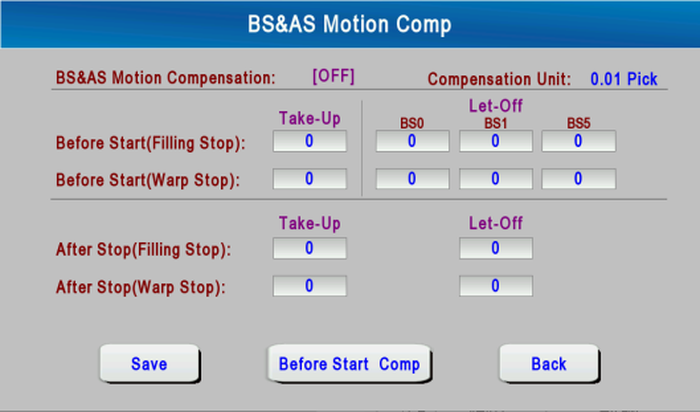
Press " BS & AS Motion Compensation" on the "ELO-ETU" screen to go to the following screen.
This function means that we can eliminate starting marks and stop marks to some extent by means of adjusting the additional let-off and take-up amount after loom stop or before loom start in order to make the cloth quality better. Under normal conditions, the let-off and take-up compensation is set to 0.
| No. | Parameters | Description | Default | Range[Unit] |
| 1 | BS&AS Motion Compensation | Turn on or off motion compensation for driving and parking. | OFF | OFF/ON |
| 2 | Left-Off Compensation BS0 (Filling Stop) | To set how much the warp beam will let off in addition when the start button has been pressed right after a weft stop and the machine has not started yet.A positive value denotes forward rotation; a negative value denotes reverse rotation; zero denotes no rotation. The same below. | 0 | -500 – 500 [0.01 picks] |
| 3 | Left-Off Compensation BS1 (Filling Stop) | To set how much the warp beam will let off in addition after one minute after a weft stop when the start button has been pressed and the machine has not started yet. | -500 – 500 [0.01 picks] | |
| 4 | Left-Off Compensation BS5 (Filling Stop) | To set how much the warp beam will let off in addition after 5 minutes after a weft stop when the start button has been pressed and the machine has not started yet. | 0 | -500 – 500 [0.01 picks] |
| 5 | Take-Up Compensation Before Start (Filling Stop) | To set how much the take-up roller will turn forward or reverse in addition after a weft stop when the start button has been pressed and the machine has not started yet. | 0 | -500 – 500 |
| 6 | Let-Off Compensation BS0 (Warp Stop) | To set how much the warp beam will let off in addition when the start button has been pressed right after a warp stop and the machine has not started yet. | 0 | -500 – 500 |
| 7 | Let-Off Compensation BS1 (Warp Stop) | To set how much the warp beam will let off in addition after one minute after a warp stop when the start button has been pressed and the machine has not started yet. | 0 | -500 – 500 |
| 8 | Let-Off Compensation BS5 (Warp Stop) | To set how much the warp beam will let off in addition after 5 minutes after a warp stop when the start button has been pressed and the machine has not started yet. | 0 | -500 – 500 [0.01 picks] |
| 9 | Take-Up Compensation Before Start (Warp Stop) | To set how much the take-up roller will turn forward or reverse in addition after a warp stop when the start button has been pressed and the machine has not started yet. | 0 | -500 – 500 |
| 10 | Left-Off Compensation After Stop (Filling Stop) | To set how much the warp beam will let off in addition right after a weft stop. | 0 | -500 – 500 [0.01 picks] |
| 11 | Take-Up Compensation After Stop (Filling Stop) | To set how much the take-up roller will take up in addition right after a weft stop. | 0 | -500 – 500 |
| 12 | Left-Off Compensation After Stop (Warp Stop) | To set how much the warp beam will let off in addition right after a warp stop. | 0 | -500 – 500 [0.01 picks] |
| 13 | Take-Up Compensation After Stop (Warp Stop) | To set how much the take-up roller will take up in addition right after a warp stop. | 0 | -500 – 500 [0.01 picks] |
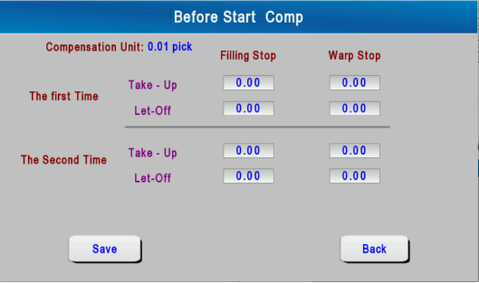
Before Start Comp:
The compensation function before driving is to set the compensation function for let-off and take-up before driving.
This function can make the warp let-off and take-up action twice before driving, and the amount of warp let-off and take-up action can be set separately for the two actions.
3.4.13 Fixed Setting
Press "Fixed Parameters" on the "ELO-ETU" screen to go to the following screen.
The loom fixed parameters are determined by the mechanical structure of the loom itself, these parameters have been set in the factory and should be not changed by the user. The accuracy of these parameters will directly affect the control precision of ELO-ETU system, thus affecting the weaving effect, so only in special cases can these parameters be modified by professionals.

| No. | Parameters | Description | Default | Range[Unit] |
| 1 | Encoder Resolution | The resolution of the ELO-ETU encoder. This parameter should be set to 255 for the 8-bit absolute encoder. | 256 | 90 – 4000 |
| 2 | Take-Up Reduction Ratio | The take-up reduction ratio. | 888 | 100 – 5000 |
| 3 | Let-Off 1 Reduction Ratio | The let-off reduction ratio of warp beam 1. | 2492 | 100 – 5000 |
| 4 | Let-Off 2 Reduction Ratio | The let-off reduction ratio of warp beam 2. | 2492 | 100 – 5000 |
| 5 | Take-up Roller Diameter | The diameter of the take-up roller. | 170 | 50 – 1000 mm |
| 6 | Max Warp Beam Diameter | The maximum diameter of the warp beam with warp yarns. | 1000 | 100 – 5000 mm |
| 7 | Min Warp Beam Diameter | The minimum diameter of the warp beam without warp yarns. | 150 | 100 – 5000 mm |
| 8 | ELO1 Motor Speed Limit | Set the maximum speed of let-off motor 1 | 3000 | 1000 – 3500rpm |
| 9 | ELO2 Motor Speed Limit | Set the maximum speed of let-off motor 2 | 3000 | 1000 – 3500rpm |
| 10 | Tension Scale 1 | Let-off 1 tension magnification factor | 100 | 90 – 300% |
| 11 | Tension Scale 2 | Let-off 1 tension magnification factor | 100 | 90 – 300% |
| 12 | Left-Off Compensation After Stop (Warp Stop) | To set how much the warp beam will let off in addition right after a warp stop. | 0 | -500 – 500 [0.01 picks] |
| 13 | Take-Up Compensation After Stop (Warp Stop) | To set how much the take-up roller will take up in addition right after a warp stop. | 0 | -500 – 500 [0.01 picks] |
3.4.14 Other Setting
The control system supports batching motion with the package. Click the 9th item in the parameter setting main screen to enter the batching motion setting screen. If the model is not equipped with a batching motion, you can not enter the batching motion setup screen.
For the specific batching motion parameter setting this article does not describe in detail.
3.5 Manual Let-off and Take-up
The system can be manually by clicking on the display button and let-off and take-up operation.
In the status window, press the [ELO-ETU] key to enter the manual feed screen.The upper part of the screen shows the current warp set tension and actual tension, the upper limit of tension and the lower limit of tension. At the bottom of the screen are 6 buttons, When the loom is in the non-woven state, it is used to control the operation of the let-off and take-up motors to adjust the tension of the cloth surface and the position of the loom.

Manual Let-off and Take-up
When pressing the button, send or take the motor action; release the button, send or take the motor to stop the action.
| No. | Parameters | Description |
| 1 |
|
Tight button. When the warp tension is greater than the set tension, the take-up roll does not move. |
| 2 |
|
Loose button. When the warp tension is less than the lower limit of tension, the take-up roller does not move. |
| 3 |
|
Loose button. When the warp tension is less than the lower limit of tension, the let-off axis does not move. |
| 4 |
|
Tight button. When the warp tension is greater than the upper limit of tension, the let-off axis does not move. |
| 5 |
|
Forward linkage button. The take-up roller and the let-off shaft synchronously rotate in the forward direction, keeping the tension unchanged. |
| 6 |
|
Reverse linkage button. The take-up roller and let-off shaft synchronously rotate in opposite directions, keeping the tension unchanged. |


3.6 Pattern Programming
Press [Dobby] or [Color] in the status window to go to the pattern editor.
The pattern editor includes the following areas:
Pattern name and number, pattern storage location, harness frame number, pattern line number, pattern total lines, active pattern flag, pattern programming area, edit menu, main menu. The color editing area also includes the cramming and multiple pick density settings. This system can be used to set up to 20 harness frames and 8 kinds of color and pick density.
3.6.1 Pattern Editor
Dobby setting:
In the dobby editing area, you can set the state of each harness frame by pressing the corresponding grid cell. The marked grip cell (white) indicates the harness frame is in higher position and the unmarked grid cell (gray) indicates the harness frame is in lower position.
Press [Up] or [Down] to view the previous page or the next page. You can also jump directly to the specified location by pressing the "Goto" button on the main menu at the bottom of the screen.
Color setting:
In the color editing area, you can set the state of each color needle by pressing the corresponding grid cell. The marked grip cell (white) indicates the corresponding needle is selected and the unmarked grid cell (gray) indicates the corresponding color needle is not selected. You can select two color needles at the same time in the same line if the "Empty/Double Weft" function is on.
The input method of cramming and multiple pick density is the same with the above. Eight kinds of pick density can be set.
Note:
If the sequence number of one harness frame in the pattern is larger than the parameter "Harness Frame Number", then this harness frame will be ignored and the control system will not control the harness frame. Please see section 3.4.5"Shed Movment" for the max harness frame number setting.
The maximum number of rows is 25400.


3.6.2 Read Pattern
"Read Pattern" means reading pattern data from the interior of the MCB or U disk. Press [Open] to go to the "Open MCB Pattern" screen or press [U Disk]->[Open Pattern] to go to the "Open USB Disk Pattern" screen. There are six sets of patterns to choose from in the internal pattern of the main board.The pattern marked with an asterisk is the pattern currently being executed. One U disk can store 200 patterns. Click the pattern list to select a pattern, the red arrow indicates the current selected pattern, it can be read or delete. Note that the current using pattern can't be deleted.

Read a Pattern from MCB

Read a Pattern from USB
3.6.3 Save Pattern
If you want save the pattern after editing and keep the same name and the location of the pattern, press [Save] on the pattern programming screen and you can set the pattern as an active one.
Pattern Name: The pattern name can be up to eight characters which can be numbers or letters.
Save to: You can choose to save the pattern in MCB or U disk.
Save as active pattern: Set the current pattern as the active pattern. If the pattern is saved in the U disk, it can not be set as the active pattern.
Pattern execution mode: Choose whether to execute the pattern from the beginning or continue from the current running position.
If you press [Back] directly without saving after editing the pattern, the screen will prompt whether to save the pattern. If you choose [Just quit], the pattern will not be modified and the HMI will return to the status window; if you choose [Save before quit], the pattern will be saved first before the HMI return to the status window.
Note: Can not modify the executing pattern during weaving.

Save Pattern
3.6.4 Locate Pattern
"Locate Pattern" is to jump directly to the specified line in the pattern.
Press [Goto] and select the location to jump by clicking on one of the gray boxes in the pop-up dialog window, then press [OK] to locate the pattern. There are three options here, jump to the first line, jump to the specified line and jump to the end line.

Locate Pattern
3.6.5 Copy Pattern
This function is used to copy the selected pattern lines for multiple cycles and insert them after the specified line. Press [Copy] and a pop-up dialog box will appear. Take color copy for example, the left side of the dialog box is the operating range selection area including four options, "All", "Color", "Density" and "Cramming". Input the start line number and end line number to copy, the number of cycles, the position to insert after and choose the copy mode on the right side of the dialog box, then press [OK] to copy the selected lines (including the start line and end line), and decide whether to insert the copied data after the specified line or overwrite the original pattern after the specified line. The "Cycles" means the number of times the selected data is copied. If you select the "Rewrite" mode, the copied data will begin to fill the pattern from the specified line (not including the line) and the original data of the pattern will be rewrite; if you select the "Insert" mode, then the copied data will be inserted after the specified line, and the original data of the pattern after the specified line will be moved backward.

Copy Pattern
3.6.6 Insert Pattern
"Insert" means to insert blank lines after the appointed line. Press [Insert] and input the number of blank lines to insert and the number of the line to insert blank lines after in the popup dialog box, and press [OK] to finish this operation.

Insert Pattern
3.6.7 Delete Pattern
This function is use to delete the selected lines of the pattern. Press [Delete] on the pattern screen, select the range of the operation on the left side of the pop-up dialog box and input the start line number and end line number on the right side of the dialog box, then select the delete mode and press [OK] to finish this operation. If you select the "Clear & Move Upward" mode, the pattern date below the end line to delete will be moved upward; if you select "Clear & Move Upward" mode, the pattern data below the lines to delete will move upward; if you select "Only Clear Data" mode, then the pattern data to delete will be just cleared and the other pattern data will remain intact.

Delete Pattern
3.6.8 Invert Dobby Pattern
"Invert" means to invert the state of the dobby grid cell so that the harness frame state is inverted too. Press [Invert] and press [OK] in the pop-up dialog box to invert dobby pattern.

Invert Dobby Pattern
3.6.9 Move Dobby Pattern
"Move" means moving the dobby pattern leftwards or rightwards from the appointed column. Press [Move] to do this.
If you choose to move rightwards, then all the dobby data on the right side of the appointed column (including itself) will move one column rightwards, the appointed column will become blank;
if you choose to move leftwards, then all the dobby data on the left side of the appointed column (including itself) will move one column leftwards and the data of the left side column next to the appointed one will be overwrote.

Move Dobby Pattern
3.6.10 Clear Pattern
"Clear" means to clear the pattern data partly or completely. Press [Clear] and select the operation range in the pop-up dialog box and press [OK] to clear the pattern data.
It is recommended to clear pattern data first before programming a new pattern to ensure the validity of the pattern data.

Clear Pattern
3.6.11 Replace Color Pattern
This operation will replace one pick number by other specified pick no. Press [Replace] and input the color number to be replaced and the color number to be replaced by in the pop-up window, and then press [OK] to finish this operation.

Replace Color Pattern
3.6.12 Double Weft and Empty Weft Programming
If you want to use this function, please ensure that this function is enabled on the "Function Option" screen.
Double Weft Weaving:Two weft yarns are insert into the same cloth fell at the same time during one weft insertion cycle. If no weft or only one weft yarn is insert into the cloth fell during double weft cycle, the loom will stop automatically. If you want to use this function, you only need to select two pick number in the same line of the color pattern. If the number of the selected pick in one line is more than two, the system will only use the first two pick numbers.
Empty Weft Weaving: This function means that the loom insert no weft yarn into the fell during normal weaving process to meet some special requirements. If there is a weft yarn inserting into the fell, the loom will stop during empty weft cycle. If you want to use this function, you only need to confirm that the specified line of the color pattern is blank.
3.6.13 Cramming and Density Programming
If you want to use the cramming and multiple pick density functions in the color editing area, you must open these two functions on the "Function Option" screen.
Cramming Setting:If you want to use the cramming function, you only need to press the cell of the cramming area and make it highlight thus the loom will stop take-up motion when the cramming program is executed.
Multiple Pick Density Setting:If you want to use this function, you can set the pick density number (corresponding to the pick density number on the "Pick Density & Warp Tension" screen) on the color pattern screen, the range is from 0 to 7. When the color pattern is executed, the weaving pick density will change synchronously corresponding to the density setting of the currently executing pattern line.
3.7 U Disk Operation
This control system supports using a U disk to store the pattern file and supports these operations of the pattern file: read, save, create, delete. This system can read the first 200 pattern files, the file extension is "*.BIN". The pattern file name should not more than eight characters. The user can use the specified pattern editing software to edit the pattern and copy it to a U disk. The user can also edit the pattern on the HMI directly and save it to the U disk, and view it on your computer or other loom.
Make sure that the U disk is inserted in the USB socket on the MCB, and do not unplug the U disk when it is in working state, or that may cause data loss or hardware damage.
Press [U disk] on the pattern editing screen to go to the USB disk operation screen. There are three menus here: open pattern, delete pattern, USB disk Info. The current connection state of the U disk is displayed below the menus, and the two states are "No Connection" or "Ready".

3.7.1 Open Pattern
Press "(1) Open Pattern" on the "USB Disk Operation" screen to go to the "Open USB Pattern" screen. The screen displays the names and sizes (expressed as the number of rows) of the pattern files in the U disk with displaying eight files per page. The current page number and total number of pages are displayed at the bottom of the screen and you can press the page up or page down button to switch pages. Click the pattern list to select a pattern, the red arrow indicates the current selected pattern, press [Open] to read the pattern.
3.7.2 Create USB Disk Pattern
Press "(2) Create New Pattern" in the U disk operation screen to enter the new U disk pattern screen. Enter the new pattern name (up to 8 characters, all uppercase) in the screen, and then press [OK] to create a new pattern in the USB flash drive.
Note: When creating a new pattern, there should be no pattern file of the same name in the U disk. Otherwise, the file creation will fail.
3.7.3 Delete USB Disk Pattern
Press "(3) Delete Pattern" to go to the "Delete USB Disk Pattern" screen. This screen displays the information of the files in U disk. Enter the serial number of the pattern to delete on the screen and press [Delete] to delete the specified pattern.
3.7.4 U Disk Information
Press "(4) USB Disk Info" to go to the following screen. There are four items listed on the screen, including the file system type, total size,free space and the number of the patterns in U disk.
The types of the file system include FAT12, FAT16 and FAT32.
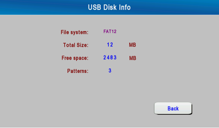
USB Disk Info
3.8 Statistics
Press [Stat] on the status window to go to the "Production Data" screen. Here you can view the production data of each shift, clear the production data, set the shift time, view the statistics data of the Filling stop and view the history report.
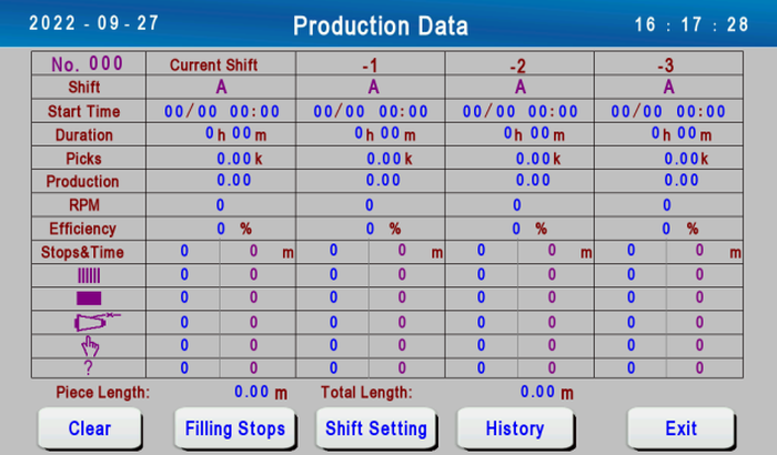
The items of the production data of each shift are shown below.
Shift: Shows the shift you are currently viewing.
Start Time: Display the start time of this shift.
Duration: Display the working hours of this shift.
Picks: Display the count of beating-up weaving after the start of the shift
Production: Shows the woven fabric length of current shift.
RPM: Show the speed of this shift
Efficiency: Shows the production efficiency of current shift. This value will be reset to 0 when a new shift start.
Stops&Time: Display the parking time and count of this shift
 : Display the number of Warp stops in this shift
 : Display the number of Filling stops in this shift
 : Display the number of Bobbin Break Stops in this shift
 : Display the number of Hand stops in this shift
 : Display the number of other reasons stops in this shift
Piece Length: Shows the woven piece length since it is cleared.
Total Length: Shows the total length of the cloth that has been woven since the last time the total length is reset to 0.
3.8.1 Reset Production Data
Press [Clear] on the "Production Data" screen to go to the "Reset Production Data" screen. You can reset the production data of each shift and reset the woven piece length and the total woven cloth length here.

3.8.2 Shift Setting
Press [Shift Setting] on the "Production Data" screen to go to the "Shift Setting" screen, here you can set the shift change mode and the start time of the first shift.
Shift Change Mode: Includes four modes, "Manual", "Two Shifts Per Day", "Three Shifts Per Day", and "Four Shifts Per Day". It is invalid that manually changing shift in the status window in the automatic shift mode. The system will change shift automatically according to the start time of the first shift and the work time of each shift. Pay attention to that the total work time of each shift should be equal to 24 hours
Shift A Start Time: Set the start time of shift A in the automatic shift mode. 24-hour clock is used here.

3.8.3 Filling Stops Data
Press [Filling Stops] on the "Production Data" screen to go to the "Filling Stop Data" screen, the weft stop times of weft detection zone 1 to 4 and the double weft stop times of each shift are displayed here.

Filling Stop Data
Press [Detail] to go to "Filling Stop & Color Data" screen to view the weft stop times and double weft stop times of each weft selector needle in the weft detection zone 1 to 4 when the weft stop of the corresponding shift occurs.

Filling Stop & Color Data
3.8.4 History Report
Press [History] on the "Production Data" screen to go to the "History Report" screen. This screen shows the production, picks, the warp stop times, the weft stop times and the production efficiency data of each shift in the past week. Press [Forward] or [Backward] to view the data of the day before or after the date displaying on the screen.

3.9 Auxiliary Function
Press [Aux] in the status window to go to the "Auxiliary Function" screen.
Auxiliary function includes pattern adjustment, time setting, system info, output signal monitoring, drive board status monitoring, backlight and beeper, SR motor startup curve, SR motor work state.

3.9.1 Pattern Adjustment
Pattern adjustment is used to change the correspondence relationship between dobby motion and weft selector motion in order to guarantee the correctness of the cloth pattern.
Press "(1) Pattern Adjustment" on the auxiliary function screen to go to the pattern adjustment screen. This screen shows the current position of the loom, the total line number of the pattern, the next line number of dobby, the next line number of color and the corresponding pattern data. Here you can change the line number of dobby or color, noting that the value must be less than or equal to the pattern length, and then press [Change] to save the current settings. Please perform this operation in the pick finding area.

Shed System:Electronic dobby or jacquard.
ELO-ETU Config: Single warp beam or double warp beam.
Filling presenter: Mechanical or normal electrical or electrical with can bus.
Electric Leno: The type of leno selvedge, three options, unused or normal or can bus.
Leno Selvedge Time: The time taken for the electronic hinge to move once, for precise control of the flat angle of the hinge.
Hot knife: Unsed, Normal, with RS485.
Motor TEMP Detection: Using or Unused
Safety Linht Curtain: Using or Unused
Loom Model:WL808
Canvas Function: Using or Unused
External Protect type: Using or Unused
PB Type: 5.5kw, 7.5kw.
Control Box Type:G1 or G2 or G3
Control Servo power: Using or Unused
Servo Feedback Mode: Using,TGON,Zero Speed
Total work time: The total accumulated power-on time since the first power-on of the weaving machinery control box.
Power on time: the total power-on time until the current time after the last time the weaving electrical control box is energized.
This system supports the use of U disk to update the main control program and operation interface, click [Update MCB Software] and [Update HMI Software] to enter the corresponding update screen respectively. Please contact the manufacturer for specific update procedures.
3.9.4 Output Signal Monitoring
Press "(4) Output Signal Monitoring" on the auxiliary function screen to go to the following screen. You can view the states of the output signals of the main controller on this screen and judge the action correctness of the loom. the green circle indicates the output signal is valid and the gray circle indicates no output.

3.9.5 Drive Board Status Monitoring
Press "(5) Drive Board Status Monitoring" on the auxiliary function screen to go to the following screen. Here you can view all kinds of fault state of the drive board. When a fault occurs, the indicator lamp corresponding to the fault will light.

3.9.6 Backlight and Beeper
Press "(6) Backlight and Beeper" on the auxiliary function screen to go to the following screen. On this screen you can set the lighting time of the backlight and whether to use the beeper. These settings will take effect immediately after the change.

3.9.7 SR Motor Startup Curve
Press "(7) SR Motor Startup Curve" on the auxiliary function screen to go to the following screen. This screen shows the actual speed curve of the loom in one second after the loom starts, which helps the related staff to better understand the loom start conditions.

3.9.8 SR Motor Work State
Press "(8) SR Motor Work State" on the auxiliary function screen to go to the following screen.

This screen lists the following items:
Current: Current value of main motor AC phase and BD phase when the motor is energized.
Voltage: Voltage value on the DC bus of the main motor driver board.
Oil temperature: oil temperature.
Motor rotor move-out time: The time taken for the main motor rotor to move from the weave position to the weft position.
Motor rotor move-in time: The time taken for the main motor rotor to move from the weft pick-up position to the weaving position.
SR motor Position: The current relative angular position of the main motor rotor for test purposes.
Motor temperature: The current temperature of the main motor.
Main motor temperature alarm: The main motor current temperature exceeds the set threshold or temperature sensor short-circuit, the alarm will be displayed.
Motor temperature alarm threshold: Displays the main motor temperature setting threshold.
3.9.9 Trial Run
Press "(9) Trial Run" on the main screen of auxiliary function to enter the test run function screen.
The test run function is a function developed for the convenience of the test run. After the test run mode is turned on, the weft and warp yarns can not be tested when the test run mode is turned on, and the warp yarn tension is not tested in this mode.
Trial Run Function: The trial run function can be turned on and off.
Filling detection: select whether to inspect the weft for the test run.
Warp detection: select whether to detect warp breaks during test runs.
Servo detection: select the servo signal when testing

3.9.10 Warp Tension Chart
Press "(10) Warp Tension Graph" on the main screen of auxiliary function to enter the warp tension graph screen. The warp tension graph will record the warp tension corresponding to each moment and save the warp tension record of the day.

3.9.11 Signal Lamp Config
Press "(11) Signal lamp config" on the main screen of auxiliary function to enter the signal lamp configuration screen. Here the user can set the state of the loom signal light corresponding to the loom in various states.
The signal lights of each color have four states: off, on, slow flashing (1Hz), and fast flashing (2Hz). If the user wants to restore the configuration to the factory state, just press the [Reset To Default] button.

3.9.12 PDF Files
Press "(12) PDF File " on the main screen of auxiliary function to enter the PDF file browsing screen. This screen can browse PDF files, insert the U disk into the USB port of the touch screen, enter the PDF file browsing screen, select the file to be viewed, and select Browse to view the PDF file.
3.9.13 Copy Parmmeter
Press "(13) U Disk Parameter Copy" on the main screen of auxiliary function to enter the U disk parameter copy screen. This function can copy the selected parameters from the U disk to the main control board, or select the parameters from the main control board to save to the U disk.

3.9.14 Do Cam Leveling
For canvas looms equipped with tread plate shedding device, click "(9) Do Cam Leveling " on the main screen of auxiliary function to make the heald frame of the loom in the fully flat position.
When the loom is in the weft-finding angle range, when the loom is not leveling the healds, press the button [execute pedal leveling heald] and then the control system controls the leveling motor to make the heald frame in the leveling position; In the leveling state, press the [Execute pedal leveling] button and the control system controls the leveling motor to move in the opposite direction to release the leveling state.
3.10 Log
"Log" records the recently loom faults including the date, time and event content in order to analyze the faults of loom. Press [Log] in the status window to go to the log screen. The contents of the record are displayed in three ways here, including only displaying fault records, only displaying action records or displaying all records.
